Series / Parallel Resistor Circuits
Time limit1sMemory limit128 MB
Repeatedly merge series and parallel resistor pairs in a given circuit, then report the equivalent resistance between A and Z or -1.000 if it fails.
- Level
Medium6 of 10
- Topics
- Graph, Simulation, Implementation
- Solved
- No attempts yet
Problem
A series/parallel resistor circuit is shown below.
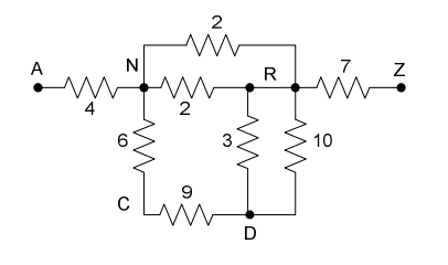
The resistance value is written next to each resistor. A connection point (a wire joining two or more resistors together) is denoted by an uppercase letter. The letters A and Z are reserved for the two connection points that are the endpoints of the circuit. Our goal is to compute the equivalent resistance of the circuit, i.e., the equivalent resistance between A and Z.
Within the circuit, a resistor can be specified by a triple consisting of the connection points at its two endpoints together with its resistance. For example, the resistor labelled could be specified as either or . A circuit specification is the set of all its resistor specifications.
Two resistors are in series if they share a common connection point that is used by no other resistor (for example, resistors and are both connected to , and nothing else is connected to ). Two series resistors can be replaced by a single equivalent resistor whose resistance is the sum of the two (in the example, ).
Two resistors are in parallel if both of their endpoints are common connection points (for example, resistors and are both connected to and to ). Two parallel resistors can be replaced by a single equivalent resistor whose resistance is the inverse of the sum of the inverses of the two resistances (in the example, ).
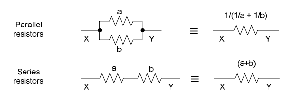
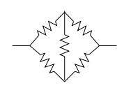
The equivalent resistance of a well-formed series-parallel circuit can be found by repeatedly replacing a series or parallel pair with its single equivalent resistor until only one resistor remains. If this technique gets stuck before reaching a single resistor, the circuit is not well-formed. For instance, a Wheatstone Bridge circuit (shown below) is not a well-formed series-parallel circuit.
Input
There may be several circuit specifications. For each circuit, the first line is an integer (), the number of resistors in the circuit. It is followed by lines, each a resistor specification of the form:
X Y r
where and are uppercase letters and is a positive integer resistance (). The equivalent resistance is guaranteed never to exceed . A line containing a single terminates the input.
Output
For each circuit, if it is well-formed and reduces to a single equivalent resistance between and , print that equivalent resistance rounded to and shown with exactly decimal places. If the circuit is not well-formed, or if there is no equivalent resistance between and , print -1.000 instead. Do not print blank lines between outputs.