Cycle
Time limit1sMemory limit128 MB
Simulate the given ICPC program with pipelined fetch, decode, and execute stages and report total cycles, or error on 16-bit overflow.
- Level
Medium6 of 10
- Topics
- Simulation, Implementation
- Solved
- No attempts yet
Problem
A small Von Neumann machine named ICPC is a 16-bit integer computer. It has plenty of instruction memory but only a single data memory cell, written M. ICPC has six registers: R1, R2, R3, R4, R5, and PC. R1 through R5 are general purpose; PC is the program counter, which holds the address of the next instruction and can be changed only by control-flow instructions.
The machine follows the usual fetch, decode, execute cycle. PC normally advances automatically, except at control-flow instructions. ICPC has two addressing modes, immediate value and register, but PC can never be used as an operand. The full instruction set is shown below, where r is a register, v is a register or an integer value, and M is the data memory cell.
Each loop is closed by pool, and each cond is closed by dnoc; the enclosed instructions are the ones executed while the condition holds.
Every stage of the fetch-decode-execute cycle is called a cycle. Each instruction therefore takes at least three cycles, and every instruction except dnoc takes exactly three cycles. dnoc only marks the end of a cond and is never executed; it is a pseudo instruction, the only one in ICPC. pool marks the end of a loop like dnoc, but it really is executed, because control must return to the top of the loop.
To shorten running time, ICPC uses pipelining. Suppose three instructions A, B, and C run in sequence. The decode stage of A can overlap the fetch stage of B, and the execute stage of A can overlap the decode stage of B and the fetch stage of C. So one move followed by one add takes only 4 cycles instead of 6, as shown by the first two instructions of Figure 1(a). In the figure, F is fetch, D is decode, and E is execute.
Pipelining stalls whenever PC reaches a control-flow instruction, because the next instruction is unknown until that control-flow instruction has been executed. The cond in Figure 1(a) shows this. Note that dnoc is never executed, and Figure 1(a) takes 9 cycles in total.
pool is a control-flow instruction as well. In Figure 1(b), both loop and pool stall the pipeline.
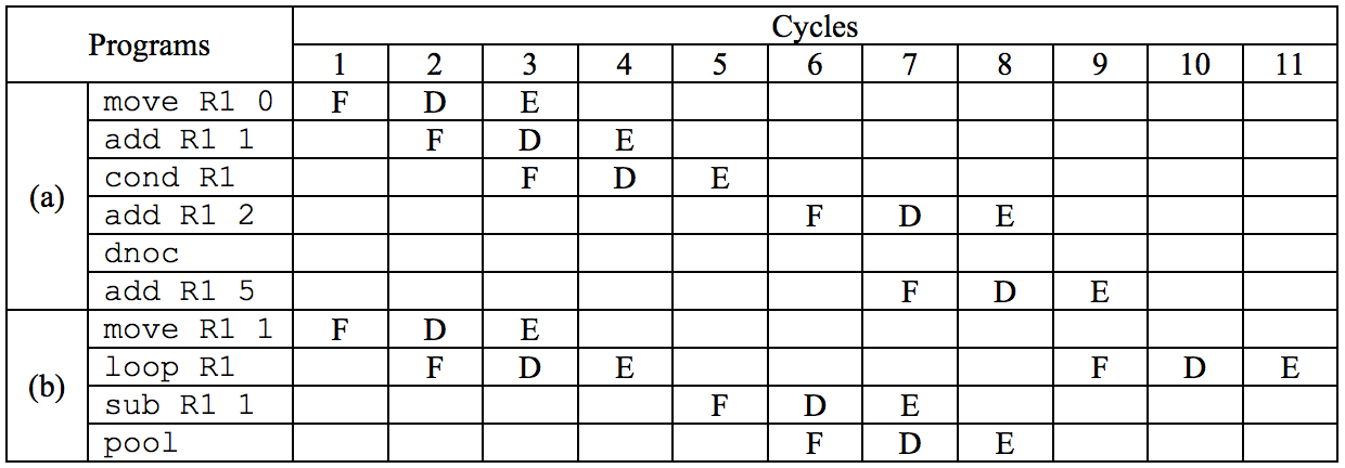
Figure 1: example programs and their cycle counts.
Input
The first line contains the number of test cases T. Each test case starts with a line containing the number of instruction lines L (L > 0), followed by L lines that hold the instruction sequence, one instruction per line.
Lines may be indented to show the nesting of control structures. Every loop and every cond contains at least one instruction, so there is no empty loop or empty branch. Each input line has at most 100 characters. Immediate values are 16-bit two's complement integers, that is . The opcode and its operands are separated by at least one blank. No test case contains an infinite loop.
Output
For each test case, print the number of cycles needed to run the given ICPC program. The data memory cell and all registers start at 0. If any register or the data memory cell overflows or underflows at any point, print error instead of a cycle count.