SV Filters
Time limit1sMemory limit256 MB
Compute the max flow between nodes 0 and 1, then remove the size-P edges reachable from node 0 and compute the max flow again.
Problem
NZPC builds water filters. A filter holds a sponge like material, so you can picture it as a set of cavities joined by channels. Water flows along the channels.
A customer orders filters that limit the amount of flowing water to a specified value, called SV filters. Every filter has its own maximum flow rate, but that rate is hard to control during manufacture. NZPC first makes a filter the ordinary way. If the flow rate is too low the filter is discarded. If it is too high, particles are added at the inlet. Depending on their size and on the connection pattern, the particles block some channels. A filter that reaches the required rate is heat treated to lock the particles in place and is then delivered.
Flushing the particles out after a failed attempt takes a long time and uses a lot of water. To cut that waste, NZPC installed a CT scanner. The scanner produces an accurate map of the cavities and channels inside a filter. Write a program that reads such a map and computes how the flow changes when particles are added.
To keep the task manageable, assume the following.
- All sizes and flow rates are integers.
- Every cavity is large enough for the largest particle to pass through freely.
- A particle blocks a channel by getting stuck in it. This happens only when the size of the particle equals the capacity of the channel exactly.
- A particle larger than the capacity cannot pass through the channel and does not block it.
- A particle smaller than the capacity passes through the channel freely.
- The map is a graph whose nodes are cavities and whose edges are channels. Node is the inlet and node is the outlet.
- Each channel has one integer capacity , the maximum flow rate through that channel.
- Water can flow in either direction through a channel.
Enough particles of size are poured into the inlet that every channel of capacity the particles can reach becomes blocked. Stated precisely:
- A node is reachable if you can get to it from node using only channels whose capacity is greater than .
- A channel of capacity exactly is blocked when at least one of its two endpoints is reachable. For this test, the outlet node counts as an ordinary cavity.
- Every other channel stays open.
Delete all blocked channels and compute the maximum flow from the inlet to the outlet again. That value is the flow after the particles are added.
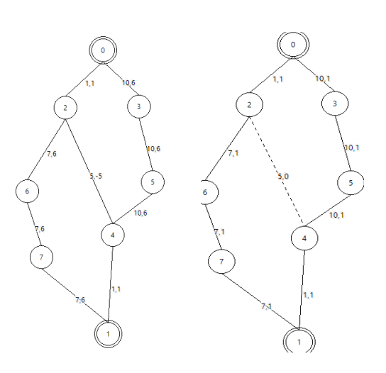
The figure draws the first example. The number on a node is its index, and the two numbers on an edge are the capacity and the actual flow. In the left graph the maximum flow from the inlet to the outlet is . The flow on the edge between node and node is written as a negative value, which means it runs uphill in the drawing. The right graph shows the system after particles of size were added. The edge between node and node is blocked and is drawn as a dashed line, and the maximum flow has dropped to .
Input
The input holds a series of filters. Each filter starts with a line containing the integers , and . is the number of cavities, is the number of channels, and is the size of the particles that will be put into the filter.
The next lines describe one channel each. A line holds three integers: the indices of the two cavities the channel connects, and the capacity of the channel. Cavities are indexed from to , cavity is the inlet and cavity is the outlet. The capacity is a positive integer. Two cavities may be connected by more than one channel.
The input ends with a line holding three zeroes.
Output
For each filter print two integers on one line, separated by a space. The first is the maximum flow through the unmodified filter. The second is the maximum flow after particles of size have been added.