The program counts interior lattice points of a polygonal workpiece that survive one full rotation against a second rotating polygonal cutter.
Hard9GeometrySimulationIntervalsNo attempts yetTime limit3sMemory limit256 MBMachine tool technology keeps advancing. One recent proposal is a more flexible lathe in which the cutter bit rotates together with the workpiece, around two parallel axles, in synchronization. When the lathe is switched on, the workpiece and the cutter bit start rotating at the same angular velocity, that is, in the same direction and at the same rotational speed. Wherever the cutter bit meets the workpiece, the overlapping part of the workpiece is cut away.
To show that the mechanism is useful, simulate the cutting process of such a lathe.
The workpiece and the cutter bit may have complicated shapes, but looking at their cross sections on a plane perpendicular to the two axles is enough. Put an xy coordinate system on that plane, with the center of rotation of the workpiece at the origin (0,0) and the center of rotation of the cutter bit at (L,0). Both cross sections are polygons, not necessarily convex.
Even when the cross section of the workpiece is split into two or more parts, the workpiece stays connected on other cross sections, so no piece falls off.
A lattice point, a point whose x and y coordinates are both integers, that lies strictly inside the workpiece before the rotation, that is, inside it and not on an edge, is called a point of interest, or POI for short.
Count how many POI remain after the workpiece and the cutter bit each complete one full rotation of 360 degrees. A POI remains if it lies strictly inside the resulting workpiece. Write a program that counts them for the given workpiece and cutter bit configuration.

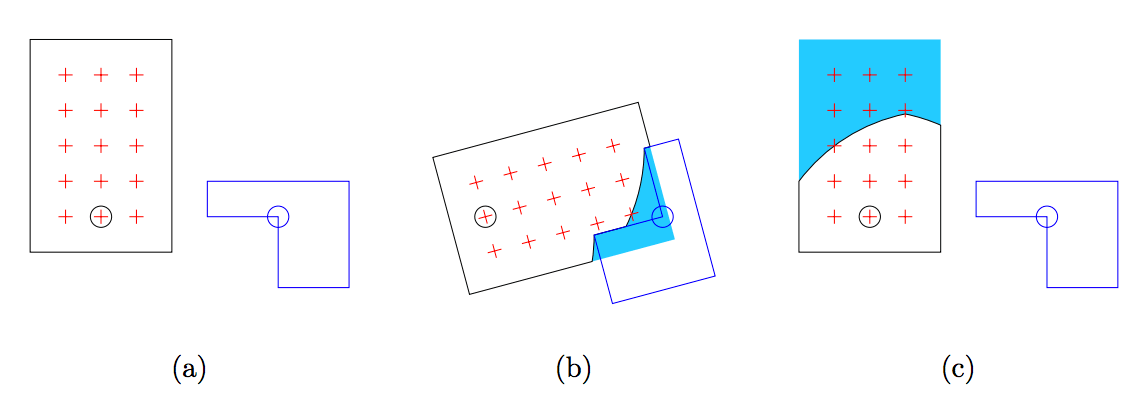
Figure 1. The workpiece and the cutter bit in the first example
Figure 1(a) shows the workpiece (black line) and the cutter bit (blue line) of the first example input. The two circles mark the two centers of rotation, and the red cross marks are the POI. Figure 1(b) shows the two shapes partway through a clockwise rotation, with the light blue area already cut off. Figure 1(c) shows the result. One POI lies on an edge of the resulting shape, and that point is not counted. Eight POI remain.
The input consists of a single test case in the following format.
M N L
xw1 yw1
.
.
.
xwM ywM
xc1 yc1
.
.
.
xcN ycN
The first line contains three integers. M is the number of vertices of the workpiece, with 4≤M≤20. N is the number of vertices of the cutter bit, with 4≤N≤20. L specifies the position of the center of rotation of the cutter bit, with 1≤L≤10000.
Each of the following M lines contains two integers. The i-th line holds xwi and ywi, telling that the i-th vertex of the workpiece is at (xwi,ywi). The vertices are given in counter-clockwise order.
The next N lines give the vertices of the cutter bit in the same manner, except that the coordinates are offsets from its center of rotation (L,0). That is, the j-th vertex of the cutter bit is at (L+xcj,ycj).
For 1≤i≤M and 1≤j≤N, −10000≤xwi,ywi,xcj,ycj≤10000.
Before the rotation starts, every edge of the workpiece and of the cutter bit is parallel to the x-axis or to the y-axis. That is, with i′=(imodM)+1, every i with 1≤i≤M satisfies xwi=xwi′ or ywi=ywi′. Edges parallel to the x-axis and edges parallel to the y-axis alternate. The same holds for the cutter bit.
The cross section of the workpiece is a simple polygon, that is, no two edges have a common point except for adjacent edges. The same holds for the cutter bit. The workpiece and the cutter bit neither touch nor overlap before the rotation starts.
(0,0) is not always inside the workpiece, and (L,0) is not always inside the cutter bit.
Print the number of POI that remain strictly inside the workpiece.