Linear Feedback Shift Register
Time limit2sMemory limit512 MB
Given an N-bit linear feedback shift register, its taps, and two states, find the minimum number of clock pulses to reach the final state, or report that it is impossible.
- Level
Medium6 of 10
- Topics
- Bit manipulation, Math, Simulation
- Solved
- No attempts yet
Problem
A shift register is a circuit that shifts the elements of a bit vector by one position. A shift register has one input bit and one output bit, and a clock pulse drives it. When a pulse occurs, the input bit becomes the most significant bit of the vector (bit ), the least significant bit (bit 0) is pushed out as the output of the register, and every other bit moves one position toward the least significant bit (toward the output).
A linear feedback shift register (LFSR) is a shift register whose input bit is the exclusive OR (XOR) of some of the register's bits just before the clock pulse. The bits used for the feedback are called taps. The figure below shows an 8-bit LFSR with three taps (bits 0, 3, and 5) over three pulses. The rightmost cell is bit 0.
If the state is written as an integer , the state after one pulse is , where is the XOR of the tap bits of .
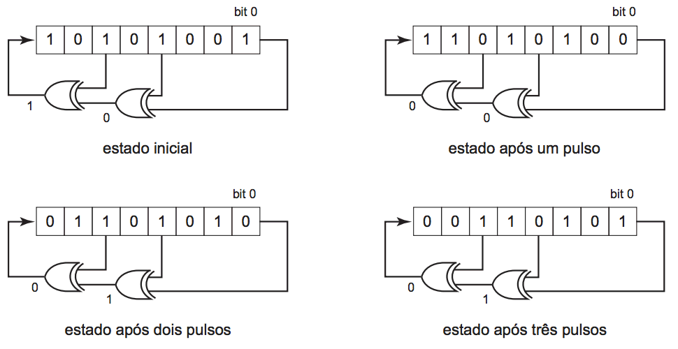
Write a program that, given the number of bits of an LFSR, the bits that are taps, an initial state, and a final state, finds the minimum number of clock pulses the LFSR needs to go from the initial state to the final state, or determines that this is impossible.
Input
The input contains several test cases. Each test case has three lines. The first line contains two integers and : the number of bits () and the number of taps (). Bits are numbered with integers from 0 (the least significant bit) to (the most significant bit). The second line contains space-separated integers in increasing order: the numbers of the bits that are taps. Bit 0 is always a tap. The third line contains two hexadecimal numbers and separated by a single space: the initial state and the final state of the LFSR. Both values fit in bits, and the hexadecimal letters can be uppercase or lowercase.
The last line of the input contains two zeros separated by a space.
Output
For each test case, print one line. If the final state can be reached from the initial state, print a single integer: the minimum number of clock pulses the LFSR needs to reach the final state. Otherwise, print only the character *.