 cho.sh
Two-Wheel Buggy
Simulate a two-wheeled buggy through N timed wheel-speed instructions and print the final axle position to five decimals.
Medium5GeometrySimulationMathNo attempts yetTime limit8sMemory limit512 MBProblem
The car maker International Car Production Company (ICPC) is developing a new vehicle called Two-Wheel Buggy. As the name says, the vehicle has only two wheels. The buggy is made of a left wheel, a right wheel, and an axle, which is a bar joining the two wheels.
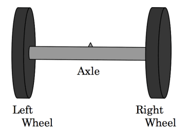
Figure 1: The basic structure of the buggy
Before building a prototype, the company decided to run a computer simulation. The rules of the simulation are below.
The buggy moves on the x-y plane. Let be the distance from the center of the axle to each wheel. When the simulation starts, the center of the axle is at , the left wheel is at , the right wheel is at , and the buggy faces the positive direction. Both wheels have radius 1.
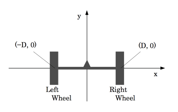
Figure 2: The initial position of the buggy
A sequence of instructions controls the movement of the buggy. One instruction is three numbers, , , and . and are the rotation speeds of the left wheel and the right wheel in degrees per second, and is how many seconds the two wheels keep those speeds. A positive speed turns a wheel in the direction that drives the buggy forward, and a negative speed turns it the other way. For example, with set to , the left wheel makes one full turn per second in the direction that drives the buggy backward. You can set and to different values, and the buggy then turns left or right. You can also set one of them positive and the other negative. The buggy then spins around.
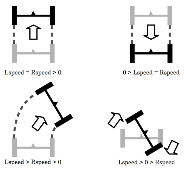
Figure 3: Examples of movement
Write a program that computes the final position of the buggy for a given instruction sequence. Assume the wheels have no width and never slip.
Input
The input holds several datasets. Each dataset has the form below.
N D
Lspeed_1 Rspeed_1 time_1
...
Lspeed_N Rspeed_N time_N
The first line of a dataset holds two positive integers and (, ). is the number of instructions, and is the distance from the center of the axle to each wheel. Each of the next lines holds three integers , , and (, ) describing the -th instruction. The sum of within one dataset is at most 500.
A line holding two zeros marks the end of the input. That line is not a dataset, so do not process it.
Output
For each dataset, print the final position of the center of the axle on two lines. Print the x-coordinate on the first line and the y-coordinate on the second line. Round both coordinates to exactly five digits after the decimal point. When a rounded coordinate is zero, print 0.00000 and not -0.00000. Print no other characters.