Gates of uncertainty
Time limit1sMemory limit1024 MB
Given a binary tree of two-input NAND gates where some gates may be stuck, count input assignments that make the faulty circuit differ from the fault-free one.
- Level
Medium7 of 10
- Topics
- Tree, Dynamic programming, DFS
- Solved
- No attempts yet
Problem
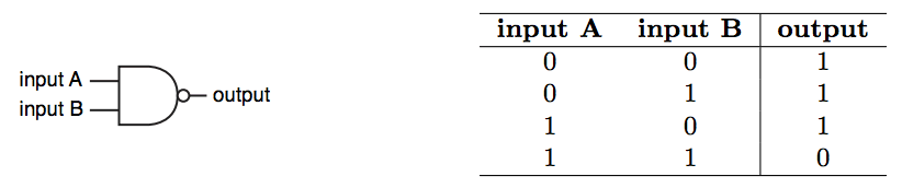
A NAND gate (negative-AND gate) is a digital circuit whose output is false only when all of its inputs are true. For the same inputs it produces the complement of the value an AND gate produces. The picture below shows the usual symbol of a two-input NAND gate and its truth table, written with 1 for true and 0 for false.
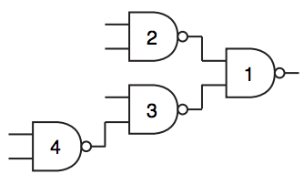
The circuit in this problem is built only from two-input NAND gates and has the shape of a binary tree. Each internal node of the tree is a NAND gate that takes the values produced by its two children as its inputs. Each leaf of the tree is one external input of the circuit and holds the value 0 or 1. The value produced by the circuit is the value produced by the gate at the root of the tree. The picture below shows a circuit with nine nodes. Four of them are NAND gates and five of them are external inputs.
A gate of the circuit may be stuck, which means it always produces 0 or always produces 1 no matter what its inputs are. Call the circuit of the same shape in which every gate works correctly the fault free circuit. A test pattern is an assignment of values to the external inputs for which the stuck gates make the circuit produce a value different from the value the fault free circuit produces.
Given the description of a circuit, write a program that counts the different test patterns.
Input
The first line contains an integer (), the number of gates in the circuit. The circuit has the shape of a binary tree. Gates are identified by distinct integers from 1 to , and gate 1 is the root of the tree. For , the -th of the next lines describes gate with three integers , and (, ). The values and are the two inputs of the gate. If is 0, the first input comes from an external input, otherwise it is the value produced by gate . The value describes the second input in the same way. Each position that holds 0 corresponds to its own external input. is the state of the gate. A value of means the gate is well behaved, 0 means the gate is stuck at 0, and 1 means the gate is stuck at 1.
Output
Print one line with the number of different test patterns of the given circuit, modulo .