CPU
Time limit1sMemory limit512 MB
Given N assembly instructions for a 16-bit CPU, print the machine code for each one by packing opcode, register, and constant fields into their bit positions.
- Level
Easy2 of 10
- Topics
- Implementation, String
- Solved
- No attempts yet
Problem
The final project for the Digital Hardware Design course is to design a 16-bit CPU and implement it in Verilog. To test whether the CPU works, you have to feed it machine code as input. Most people find machine code made only of 0s and 1s hard to read, so they write programs in languages like C++ or Java and use a compiler to translate them into machine code.
Among programming languages, assembly is the one that is easiest for people to read while staying closest to machine code. Assembly code is translated into machine code by an assembler. Assembly corresponds one to one with machine code. For example, if the assembly code for adding two numbers is ADD and its machine code is 00000, the assembler reads ADD and replaces it with 00000.
The table below shows the structure of the 16-bit instructions that Minho's CPU can process.
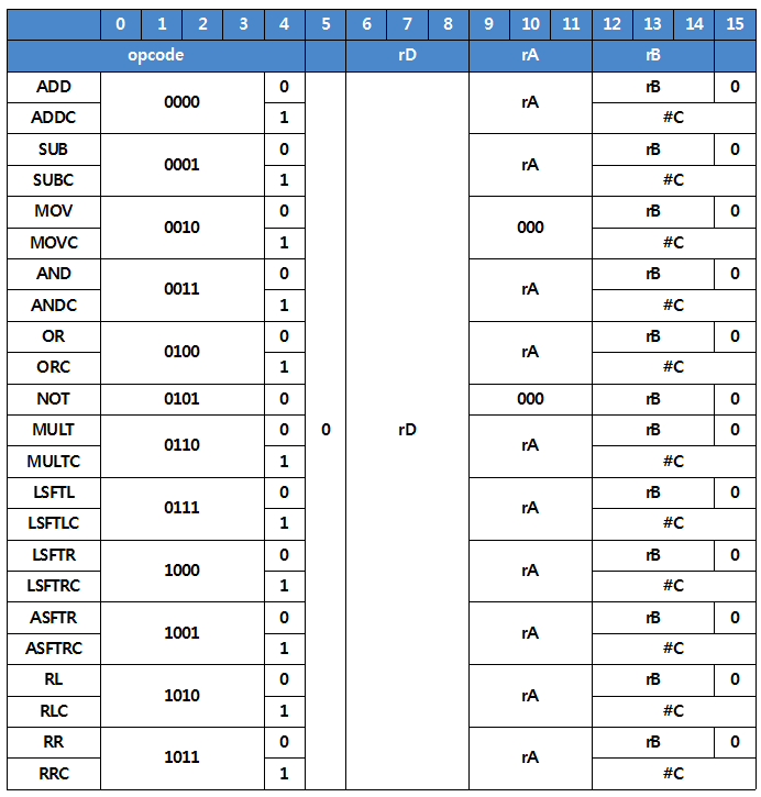
Input and output are always handled one instruction at a time. Assembly code has the form "opcode rD rA rB" or "opcode rD rA #C". In general, the operation given by the opcode is applied to the values in registers rA and rB, or to the value in rA and the constant #C, and the result is stored in register rD. Depending on the opcode, rA may not be used. The assembler converts opcode, rD, rA, rB, and #C into a 16-bit machine code of 0s and 1s, placing each field in its bit positions. The meaning of each bit is as follows.
- Bits 0 to 4: the opcode, which specifies the operation the CPU performs. If bit 4 is 0, the CPU uses register rB. If bit 4 is 1, the CPU uses the constant #C.
- Bit 5: not used, always 0.
- Bits 6 to 8: the number of register rD, which stores the result.
- Bits 9 to 11: the number of register rA used in the operation. If rA is not used, these bits are 000.
- Bits 12 to 15: if bit 4 is 0, bits 12 to 14 are the number of register rB used in the operation and bit 15 is always 0. If bit 4 is 1, bits 12 to 15 are the constant #C.
Input
The first line contains the number of instructions N (1 ≤ N ≤ 500).
Each of the next N lines contains an instruction in the form "opcode rD rA rB" or "opcode rD rA #C". The opcode is always in uppercase. Register numbers rD, rA, and rB (0 ≤ rD, rA, rB ≤ 7) are between 1 and 7, and a value is 0 only when that register is not used. The constant #C (0 ≤ #C ≤ 15) is a constant.
Output
Print N lines, each containing the 16-bit machine code translated from the corresponding instruction.