Intersection Graph
Time limit1sMemory limit256 MB
For two axis-aligned boxes, list every nonempty boundary intersection as a point, curve, or surface and output its endpoints and incidences.
- Level
Hard8 of 10
- Topics
- Geometry, Implementation, Brute force
- Solved
- No attempts yet
Problem
Innokentiy still enjoys writing geometric algorithms, but he has moved from triangular meshes to solid bodies. He wants to write an algorithm that builds the intersection graph of two bodies, which is needed, for example, to run a boolean operation on those bodies. Only the boundaries of the bodies are considered when building the graph; their interior volumes are ignored. Innokentiy knows that building the intersection graph of two arbitrary bodies is a difficult task in CAD. He has decided to start with a simpler case: learning to build the intersection graph of two boxes, and .
A box (usually called an axis-aligned box) is a rectangular parallelepiped whose sides are parallel to the coordinate axes. The boundary of a box consists of topological elements of three types:
V: a vertex, which is geometrically a point;E: an edge, which is a line segment;F: a face, which is a rectangle.
Each box has 8 vertices, 12 edges, and 6 faces.
For this problem, an edge and a face are represented by the corresponding point sets without boundary points. Thus an edge is a line segment that does not contain its endpoints, and a face is a rectangle that does not contain its corners or sides. Under this definition, the topological elements share no points, and together they form exactly the entire boundary of the box.
An intersection graph consists of interrelated intersection elements, defined as follows. Consider every pair consisting of a topological element of box and a topological element of box (676 pairs in total). For each pair , take the intersection of the two sets. If the intersection is non-empty, it defines an intersection element, which has one of three types:
p: a point, a single point;c: a curve, a set of points forming a line segment;s: a surface, a set of points forming a rectangle.
The intersection graph consists of all intersection elements obtained in this way.
The intersection elements are interconnected. For each intersection curve, the two intersection points at its ends are stored. For each intersection point, a list of intersection curves incident to that point is stored. An intersection curve is incident only to its endpoints and to no other intersection points. For each intersection surface, the set of intersection curves on its boundary (and therefore bounding it) is stored.
Input
The first line of the input file contains a single integer , the number of test cases (). It is followed by blocks.
Each block consists of two lines. The first line defines box , and the second line defines box . A box is described by six integers whose absolute values do not exceed . The numbers are the coordinates of the minimal vertex, and are the coordinates of the maximal vertex (, , ).
Output
The output file must contain the intersection graphs for the test cases in the input file. After each intersection graph, print === on a separate line. All numbers in the output file must be integers.
The description of an intersection graph contains many links between intersection elements and topological elements. To describe these links, assign a number (or index) to every element. All topological elements of box must be numbered from to in any order. Likewise, all topological elements of box must be numbered from to in any order. Also, all intersection elements must be numbered from to in the order in which they appear in the output file, where is the total number of intersection elements.
The first line of an intersection graph description must contain three numbers: , the number of intersection points; , the number of intersection curves; and , the number of intersection surfaces. Naturally, . After that, describe the intersection elements in this order: first the intersection points, then the intersection curves, and finally the intersection surfaces, with one intersection element per line.
The description of each intersection element must begin with its index, followed by a three-letter code made by the following rule.
- The first letter is the type of the intersection element:
pfor a point,cfor a curve, orsfor a surface. - The second letter is the type of topological element :
Vfor a vertex,Efor an edge, orFfor a face. - The third letter is the type of topological element .
Here and are the topological elements of boxes and , respectively, from which the intersection element was generated. Next, print two integers: the indices of and , in that order. Finally, print additional information depending on the type of the intersection element.
For an intersection point, also print its three coordinates, the number of intersection curves incident to it, and the list of indices of those curves. The indices of incident curves may be printed in any order.
For an intersection curve, also print the indices of the two intersection points at its ends. These two numbers may be printed in any order.
For an intersection surface, also print the number of intersection curves on its boundary and the list of their indices. The indices of the boundary curves may be printed in any order.
The numbers in the output file do not have to be separated by exactly one space. Several spaces in a row are allowed.
Hint
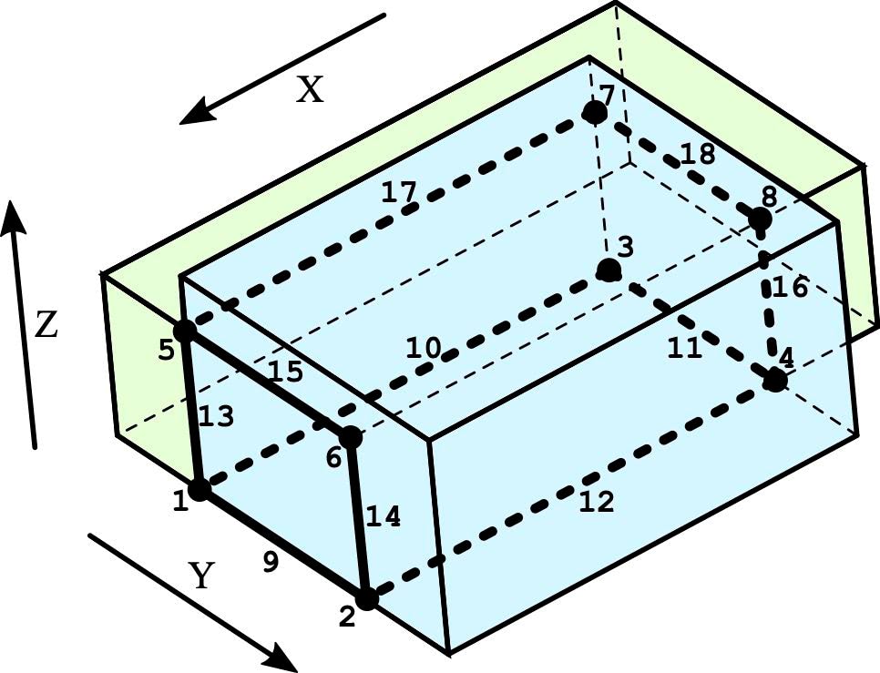
In the first test case, the boxes pass through each other at a corner. The intersection graph is drawn with bold lines. It consists of six points and six curves, hidden from the viewer by box . The indices of the intersection elements are shown.
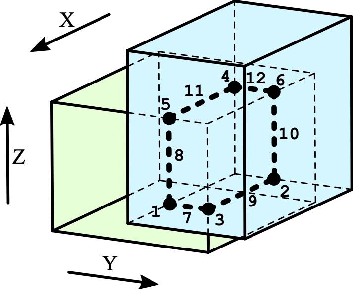
In the second test case, the boxes share their bottom and front faces, which produces intersection surfaces 19 and 20 (they are not shown in the figure). All remaining elements are shown in bold, and their indices are given.